Paper presentation on Solar power generation optimisation
Paper presentation, free papers presentation, Electrical papers presentation, electronic papers presentation, computer papers presentation, information technology papers presentation, chemical papers presentation, mechanical papers presentation, engineering papers presentation, medical papers presentation, 1000 papers presentation.
ABSTRACT:
Energy is vital for sustaining life on earth, which determines the stability of economic development of a nation. In India today we are facing a 13% deficit in the generation and demand of electrical energy. Hence there is need to optimally and economically design and develop all the possible non-conventional energy recourses to reduce the void between supply and demand of electrical power.
This paper discuss about the solar photo voltaic cells
Ø The working principle of solar photo voltaic cells.
Ø Stand alone solar photovoltaic system (SAPS).
Ø Problems in the working of SAPS.
Ø PIC based voltage regulator.
Ø Advantages.
Ø Future expansion.
.
INTRODUCTION:
Basically there are two types of power generations those are
1. Conventional energy sources.
2. Non-conventional energy sources.
Solar power generation is belongs to non-conventional energy sources.
Ø As mentioned in most power industry cycles, solar power is considered to be one of the most reliable sources of energy for centuries to come. The technology to generate electricity from solar photovoltaic has developed considerably in the past two decades.
Ø The solar photo voltaic cells have a low efficiency due to the fluctuating nature of solar radiation. The batteries connected to the output of photovoltaic arrays require constant input. But due to the incontinency the supply from panels the life of the batteries, and t the same time the efficiency of the system, is reduced.
Ø Efficiency is increased by using voltage regulator consist of peripheral interface controller (PIC) 16F876.
Ø The word "photovoltaic" is combinations of the Greek word for 'light' and name of the physicist Aleksandra Volta. Thus photovoltaic means "light to electricity"
WORKING PRINCIPLE OF PHOTOVOLTAIC CELLS:
Ø Photovoltaic cells employ a solid-state diode structure having a large area on a silicon wafer. The surface layer is very thin transparent, so that light can reach the junction region of the silicon sandwich.
Ø In that region the photons are absorbed, releasing charges from their atomic bonds. These charges migrate to the terminals, raising the potential.
Ø A single cell has an open circuit with the voltage of approximately 0.6-1.0 volts and short circuit current of a few milliamps.
SOLAR ARRAY CHARACTERISTICS:
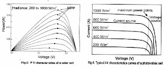
The maximum power point of a solar module changes in the solar irradiance with changes in the solar irradiance and module temperature.
The typical characteristic curve current vs. voltage and power vs. voltage of a solar cell at different levels of solar irradiation are illustrated in fig-1 .
Ø From fig -1 .It consists of two regions; one is the current source and other is voltage source region. In the voltage source region the internal impedance of the solar array is low. That region is the right side of I vs. V curve.
Ø The current source region, in which the internal impedance of the solar array is high, is at the side of the I vs. V curve. The MPP of the solar array is located at the knee of the I vs. V curve.
Ø It is observed that each curve has a MPP, which is optional point of for the efficient use of the solar array.
STAND-ALONE PHOTOVOLTAIC SYSTEM:
The stand-alone photovoltaic power system is defined as an autonomous system that supplies power without being connected to the grid.
A scheme for SAPS is shown in fig-3.A stand alone solar electric system consists of four basic parts.

Ø Photovoltaic panels: The photo voltaic panels make dc electricity, which is fed to the charge controller.
Ø Charge controller: The controller feeds the current to the batteries at regular rate.
Ø Batteries: The battery forms an important part of the solar PV system. The battery is necessary in such a system because of the fluctuating nature of the output delivered by the PV arrays.
Ø Both the batteries voltage and PV array voltage vary during operation with the atmospheric condition and the state of charge conditions.
Ø Inverter: The electricity produced by solar cells is direct current and can be used in that way, or can be converted to alternating current using inverters. Typical DC voltage levels are 12,24 and 48 volts depending on the panel output which ranges from a few watts to few kilowatts.
PROBLEMS IN WORKING OF SAPS:
Two problems raised in SAPS that are-
Ø In case of shadow being cast by an object or a cloud over the voltage generator by each set of soar cell module varies. This may affect the load conditions.
Ø A major problem of the batteries in SAPS is their inability to live up to the expectations of the user due to poor functioning of the battery charges. this includes over charging, in completing charging and prolonged operation at low state of charge-which results in increasing running costs, due to replacement of batteries before their expected lifetime.
PIC BASED VOLTAGE REGULATOR:
Ø The above problems can be over come by "VOLTAGE REGULATOR” which is used in between the photovoltaic panels and battery.
Ø The voltage regulator is" a micro controller based DC/DC step down converter used by a solar power system to charge a12 volts battery".
 CIRCUIT DESCRIPTION:
The voltage regulator circuit is divided into two basic parts-
1. DC-DC converter
2. Micro controller.
1. DC/DC BUCK CONVERTER: In general DC chopper consists of a combination of switches, inductor, capacitors, which changes v-out/v-in ratio by varying the duty cycle or frequency of switches.
2. Micro controller: the micro controller measure the PV array output current and voltage then it changes the duty cycle of the PWM.
THEORY OF OPERATION:
Solar panels design for charging 12v batteries actually generate more watts running at around 17v.By using DC/DC converter, to connect the solar panel to the battery, it allows the solar panel to run at the higher voltage-that is maximum power output than when connected directly to the battery.
The DC/DC converter is a buck converter, which means it takes higher input voltage and converts it to a lower output voltage. Since this is a switching converter topology it doesn't dissipate any power internally (expect for small resistive losses).
That means the output power is equal to the input power, Watts in=Watts out. So the watts stay the same and voltage drops, then output current must be greater than the input current.
The micro controller - a PIC16F876 -manages the conversion ratio of the DC/DC converter. The PIC generates a 100 kHz PWM signal with its internal circuit.
The ratio of the on time of the switches sets the conversion ratio of the input to the output voltage of the DC/DC converter. The PIC tries to set the conversion ratio of the DC/DC Converter to allow the solar panels to operate at their maximum PowerPoint.
The microprocessor does this using an iterative algorithm to maximize the input watts of the solar panels. Measuring voltage and current with PIC's A/D inputs and multiplying internally to gift the watts, calculate the input watts from the solar panel.
The solar panel voltage runs through a resister divider network to get it down in the 5v range of the PIC's A/D converter. The solar panel current is measure with a current sense resister and difference amplifier to condition the PIC's A/D.
The PIC can also read the voltage of the battery with another voltage divider, the flowing into the battery with another sense resister and difference amplifier.
The battery voltage is used by the PIC to tell when the battery is fully charged, the microprocessor role back the charging current to keep from over charging the battery.
The microprocessor transmit out the serial port all the it has measured and calculated (volts, amps and watts) once a second to be logged by an external computer. Every 20 seconds the PIC set the conversion ratio of DC/DC converter to 100% or full on.
This simulates a direct connection between solar panels and the battery. The solar power input watts are measured and compared the solar panel watts at output to get the gain or boost of the voltage regulator.
ADVANTAGES:
It involves no moving parts hence is simple compact and there is no maintain.
Voltage regulator supplies constant power to the batteries and helps in increasing the system efficiency.
Checks battery condition and then accordingly varies the PWM duty cycle.
PIC based voltage regulator is in simple in construction, chief and efficient.
CONCLUSION (FUTURE SCOPE):
The existing circuit does not have short protection and open circuit protection. If these two protection schemes are provided then the device will become more reliable.
An over charge alarm can be added to the device to protect batteries from over charging.
In commercial system an inverter is always present .Due to the presence of inverter transient are observed during switching. The affect the working of the device .Hence while using in the commercial schemes the device needs to be modified and correction for this should be given.
ABSTRACT:
Energy is vital for sustaining life on earth, which determines the stability of economic development of a nation. In India today we are facing a 13% deficit in the generation and demand of electrical energy. Hence there is need to optimally and economically design and develop all the possible non-conventional energy recourses to reduce the void between supply and demand of electrical power.
This paper discuss about the solar photo voltaic cells
Ø The working principle of solar photo voltaic cells.
Ø Stand alone solar photovoltaic system (SAPS).
Ø Problems in the working of SAPS.
Ø PIC based voltage regulator.
Ø Advantages.
Ø Future expansion.
.
INTRODUCTION:
Basically there are two types of power generations those are
1. Conventional energy sources.
2. Non-conventional energy sources.
Solar power generation is belongs to non-conventional energy sources.
Ø As mentioned in most power industry cycles, solar power is considered to be one of the most reliable sources of energy for centuries to come. The technology to generate electricity from solar photovoltaic has developed considerably in the past two decades.
Ø The solar photo voltaic cells have a low efficiency due to the fluctuating nature of solar radiation. The batteries connected to the output of photovoltaic arrays require constant input. But due to the incontinency the supply from panels the life of the batteries, and t the same time the efficiency of the system, is reduced.
Ø Efficiency is increased by using voltage regulator consist of peripheral interface controller (PIC) 16F876.
Ø The word "photovoltaic" is combinations of the Greek word for 'light' and name of the physicist Aleksandra Volta. Thus photovoltaic means "light to electricity"

WORKING PRINCIPLE OF PHOTOVOLTAIC CELLS:
Ø Photovoltaic cells employ a solid-state diode structure having a large area on a silicon wafer. The surface layer is very thin transparent, so that light can reach the junction region of the silicon sandwich.
Ø In that region the photons are absorbed, releasing charges from their atomic bonds. These charges migrate to the terminals, raising the potential.
Ø A single cell has an open circuit with the voltage of approximately 0.6-1.0 volts and short circuit current of a few milliamps.
SOLAR ARRAY CHARACTERISTICS:
The maximum power point of a solar module changes in the solar irradiance with changes in the solar irradiance and module temperature.
The typical characteristic curve current vs. voltage and power vs. voltage of a solar cell at different levels of solar irradiation are illustrated in fig-1 .
Ø From fig -1 .It consists of two regions; one is the current source and other is voltage source region. In the voltage source region the internal impedance of the solar array is low. That region is the right side of I vs. V curve.
Ø The current source region, in which the internal impedance of the solar array is high, is at the side of the I vs. V curve. The MPP of the solar array is located at the knee of the I vs. V curve.
Ø It is observed that each curve has a MPP, which is optional point of for the efficient use of the solar array.
STAND-ALONE PHOTOVOLTAIC SYSTEM:
The stand-alone photovoltaic power system is defined as an autonomous system that supplies power without being connected to the grid.
A scheme for SAPS is shown in fig-3.A stand alone solar electric system consists of four basic parts.

Ø Photovoltaic panels: The photo voltaic panels make dc electricity, which is fed to the charge controller.
Ø Charge controller: The controller feeds the current to the batteries at regular rate.
Ø Batteries: The battery forms an important part of the solar PV system. The battery is necessary in such a system because of the fluctuating nature of the output delivered by the PV arrays.
Ø Both the batteries voltage and PV array voltage vary during operation with the atmospheric condition and the state of charge conditions.
Ø Inverter: The electricity produced by solar cells is direct current and can be used in that way, or can be converted to alternating current using inverters. Typical DC voltage levels are 12,24 and 48 volts depending on the panel output which ranges from a few watts to few kilowatts.
PROBLEMS IN WORKING OF SAPS:
Two problems raised in SAPS that are-
Ø In case of shadow being cast by an object or a cloud over the voltage generator by each set of soar cell module varies. This may affect the load conditions.
Ø A major problem of the batteries in SAPS is their inability to live up to the expectations of the user due to poor functioning of the battery charges. this includes over charging, in completing charging and prolonged operation at low state of charge-which results in increasing running costs, due to replacement of batteries before their expected lifetime.
PIC BASED VOLTAGE REGULATOR:
Ø The above problems can be over come by "VOLTAGE REGULATOR” which is used in between the photovoltaic panels and battery.
Ø The voltage regulator is" a micro controller based DC/DC step down converter used by a solar power system to charge a12 volts battery".
 CIRCUIT DESCRIPTION:
The voltage regulator circuit is divided into two basic parts-
1. DC-DC converter
2. Micro controller.
1. DC/DC BUCK CONVERTER: In general DC chopper consists of a combination of switches, inductor, capacitors, which changes v-out/v-in ratio by varying the duty cycle or frequency of switches.
2. Micro controller: the micro controller measure the PV array output current and voltage then it changes the duty cycle of the PWM.
THEORY OF OPERATION:
Solar panels design for charging 12v batteries actually generate more watts running at around 17v.By using DC/DC converter, to connect the solar panel to the battery, it allows the solar panel to run at the higher voltage-that is maximum power output than when connected directly to the battery.
The DC/DC converter is a buck converter, which means it takes higher input voltage and converts it to a lower output voltage. Since this is a switching converter topology it doesn't dissipate any power internally (expect for small resistive losses).
That means the output power is equal to the input power, Watts in=Watts out. So the watts stay the same and voltage drops, then output current must be greater than the input current.
The micro controller - a PIC16F876 -manages the conversion ratio of the DC/DC converter. The PIC generates a 100 kHz PWM signal with its internal circuit.
The ratio of the on time of the switches sets the conversion ratio of the input to the output voltage of the DC/DC converter. The PIC tries to set the conversion ratio of the DC/DC Converter to allow the solar panels to operate at their maximum PowerPoint.
The microprocessor does this using an iterative algorithm to maximize the input watts of the solar panels. Measuring voltage and current with PIC's A/D inputs and multiplying internally to gift the watts, calculate the input watts from the solar panel.
The solar panel voltage runs through a resister divider network to get it down in the 5v range of the PIC's A/D converter. The solar panel current is measure with a current sense resister and difference amplifier to condition the PIC's A/D.
The PIC can also read the voltage of the battery with another voltage divider, the flowing into the battery with another sense resister and difference amplifier.
The battery voltage is used by the PIC to tell when the battery is fully charged, the microprocessor role back the charging current to keep from over charging the battery.
The microprocessor transmit out the serial port all the it has measured and calculated (volts, amps and watts) once a second to be logged by an external computer. Every 20 seconds the PIC set the conversion ratio of DC/DC converter to 100% or full on.
This simulates a direct connection between solar panels and the battery. The solar power input watts are measured and compared the solar panel watts at output to get the gain or boost of the voltage regulator.
ADVANTAGES:
It involves no moving parts hence is simple compact and there is no maintain.
Voltage regulator supplies constant power to the batteries and helps in increasing the system efficiency.
Checks battery condition and then accordingly varies the PWM duty cycle.
PIC based voltage regulator is in simple in construction, chief and efficient.
CONCLUSION (FUTURE SCOPE):
The existing circuit does not have short protection and open circuit protection. If these two protection schemes are provided then the device will become more reliable.
An over charge alarm can be added to the device to protect batteries from over charging.
In commercial system an inverter is always present .Due to the presence of inverter transient are observed during switching. The affect the working of the device .Hence while using in the commercial schemes the device needs to be modified and correction for this should be given.


